


- May 16th, 2016, 1:57 pm#4864195
Touché! Nice start P 
My old GB2 pack replica http://s268.photobucket.com/albums/jj16 ... ter=images
Currently building a full aluminium proton pack - w.i.p
viewtopic.php?t=38600
Now also an aluminium gb1 trap, why not!
viewtopic.php?f=3&t=42513
Currently building a full aluminium proton pack - w.i.p
viewtopic.php?t=38600
Now also an aluminium gb1 trap, why not!
viewtopic.php?f=3&t=42513
- May 18th, 2016, 4:07 pm#4864465
Not read the whole thing through so not sure if it's been mentioned. Clean your files with Sodium Hydroxide. 3 hours, clean as a whistle
Fantastic work btw.
I've been trying to choose a good material to build mine. Think full Alu is the way forward
Fantastic work btw.
I've been trying to choose a good material to build mine. Think full Alu is the way forward

- May 21st, 2016, 6:48 am#4864817
Hi all, it's late here and I've just come in from a frustrating night of building my thrower where not a lot was going well.
My fear of screwing up the handle socket welds was basically realized. They are tricky to do and I think I voodooed myself by worrying about them. The welds are far from a stack of dimes, more clumsy at best. I might sand them back and do another pass over them tomorrow if people think it's worth while. Also all the heat on the rear weld has caused the sloped face/roof joint to crack, which may have also been me over sanding too. Not sure what I'm going to do about this one.
Anyway here is the photos for tonight.
 ,
,

The rear handle is straight with the sides and roof, but it turns out the roof is not parallel to the base and the error is amplified by the length of the handle. It's out by about 5mm but not to noticeable. The following photo makes it look worse than it is.

It also turns out that the base of the Clippard is a couple of mm wider than the print out I was working from, so I ended up have to slot the mounting holes to make sure that the knob that goes beside it will fit correctly. Luck for me the Clippard covers up this minor error.
That's Spongeface bezel mounted for a test fit if anyone is curious.
Welds, welds welds. ..................
My fear of screwing up the handle socket welds was basically realized. They are tricky to do and I think I voodooed myself by worrying about them. The welds are far from a stack of dimes, more clumsy at best. I might sand them back and do another pass over them tomorrow if people think it's worth while. Also all the heat on the rear weld has caused the sloped face/roof joint to crack, which may have also been me over sanding too. Not sure what I'm going to do about this one.
Anyway here is the photos for tonight.
 ,
,
The rear handle is straight with the sides and roof, but it turns out the roof is not parallel to the base and the error is amplified by the length of the handle. It's out by about 5mm but not to noticeable. The following photo makes it look worse than it is.

It also turns out that the base of the Clippard is a couple of mm wider than the print out I was working from, so I ended up have to slot the mounting holes to make sure that the knob that goes beside it will fit correctly. Luck for me the Clippard covers up this minor error.
That's Spongeface bezel mounted for a test fit if anyone is curious.
Welds, welds welds.
barison82 liked this
- May 21st, 2016, 6:50 am#4864820
Thanks for the tip. Someone put me onto using a short length of squashed copper pipe with the grain of the file to clean out the aluminum pieces. It works a treat.
P.
DrFusion wrote:Not read the whole thing through so not sure if it's been mentioned. Clean your files with Sodium Hydroxide. 3 hours, clean as a whistleDr,
Fantastic work btw.
I've been trying to choose a good material to build mine. Think full Alu is the way forward
Thanks for the tip. Someone put me onto using a short length of squashed copper pipe with the grain of the file to clean out the aluminum pieces. It works a treat.
P.
- May 22nd, 2016, 5:36 am#4864935
Hi all.
Well after a night's rest I revisted my thrower welds. After looking at various photos on the web and a couple of supporting PMs I've decided that they will do as is.
Although the cracked weld on the sloped face needed to be fixed. My handles don't extend into the body of the thrower so that way I will have more space later for all of the bits and pieces. So I ran a weld along the cracked joint on the inside, not the prettiest but adds strength, then I ran a new weld across the top and sanded it flat again.
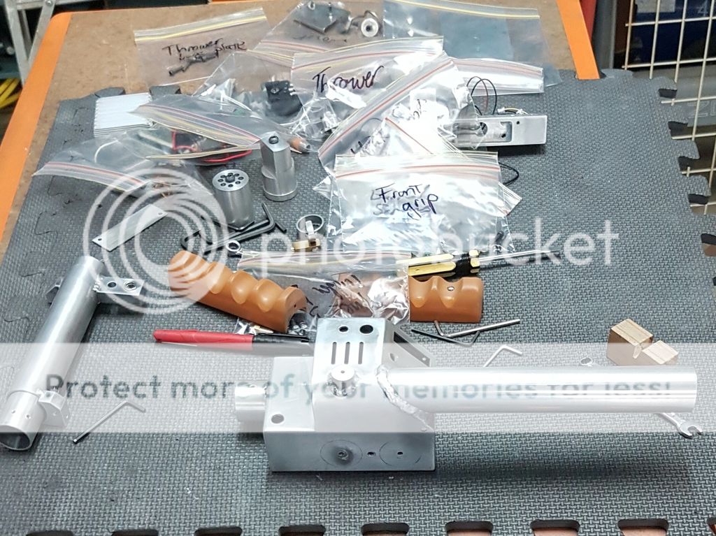
I cut the front handle inner tube and did a test fit and took a couple more photos to share with you guys.


That's all for this weekend. Constructive criticism and comments welcome as always.
P.
Well after a night's rest I revisted my thrower welds. After looking at various photos on the web and a couple of supporting PMs I've decided that they will do as is.
Although the cracked weld on the sloped face needed to be fixed. My handles don't extend into the body of the thrower so that way I will have more space later for all of the bits and pieces. So I ran a weld along the cracked joint on the inside, not the prettiest but adds strength, then I ran a new weld across the top and sanded it flat again.
I cut the front handle inner tube and did a test fit and took a couple more photos to share with you guys.


That's all for this weekend. Constructive criticism and comments welcome as always.
P.
- May 22nd, 2016, 1:39 pm#4864999
It looks fine Pete, the thrower is indeed a tricky beast Are you still using 1.6mm sheet?
My old GB2 pack replica http://s268.photobucket.com/albums/jj16 ... ter=images
Currently building a full aluminium proton pack - w.i.p
viewtopic.php?t=38600
Now also an aluminium gb1 trap, why not!
viewtopic.php?f=3&t=42513
Currently building a full aluminium proton pack - w.i.p
viewtopic.php?t=38600
Now also an aluminium gb1 trap, why not!
viewtopic.php?f=3&t=42513
- May 22nd, 2016, 5:10 pm#4865033
Yep, still working with 1.6mm plate. Makes welding that much more tricky with the heat control.
Nice to have the thrower to a point that I can hold onto it in the firing stance.
P.
OCP_Model-001 wrote:It looks fine Pete, the thrower is indeed a tricky beastHi OCP
Yep, still working with 1.6mm plate. Makes welding that much more tricky with the heat control.
Nice to have the thrower to a point that I can hold onto it in the firing stance.
P.
- May 23rd, 2016, 4:26 am#4865067
Pete
CPU64 wrote:Looks nice, yo!Thanks Chris. Out of curiosity what length do you cut the front barrels? I have a couple of different plans that show slightly different lengths.
Pete
- May 24th, 2016, 11:56 pm#4865209
It depends on the rest of the parts making up the front handle. I leave a 1/8" gap in the back end, and 1/2" up front, after the grip section is complete.
- May 26th, 2016, 2:13 pm#4865341
"Boy this equipment's heavy..."
This is an incredible feat! Absolutely beautiful! It would almost be a shame to paint it and cover up all that beautiful aluminum! I haven't been back to this thread for a while, but I love seeing how everything comes together.
"Boy this equipment's heavy..."
- July 10th, 2016, 5:25 am#4870809
Hi all, its been a little while since my last post so I thought that a few update photos is long overdue.
I've been progressing the thrower build along slowly when I have spare time. I must confess a lot slower than I would like basically because I find myself triple checking everything to try and avoid having to repeat any of the build.
Since my last post, I have welded up the font outer barrel and made and mounted the instrument box and trigger box and its finally starting to look like a thrower.
I decided that I wanted the trigger box without a door on the back like in GB1. I also decided that I don't like the look of the weld between the trigger box and instrument bar. So I came up with a bracketing arrangement that allows me to remove the trigger box from the instrument bar and access its internals for the switch wiring and doing up the switch nuts through a hole. While its a little tricky it is totally possible to mount and replace the switches etc. Anyway, I'm quite happy with the end result that looks clean.
I finished welding the outer barrel today and fitted nic-a-trons grips. While I know its not movie accurate I didn't like the sloping of the grip sides so I squared them up. The back grip is taped on at the moment (to allow me to play ) as I don't want to pop rivet it in place. Instead I'm going to buy a couple of small stainless button cap screws to mount it this week.
Anyway, enough writing, time for the pics.
Comments and constructive criticism welcome.
I've been progressing the thrower build along slowly when I have spare time. I must confess a lot slower than I would like basically because I find myself triple checking everything to try and avoid having to repeat any of the build.
Since my last post, I have welded up the font outer barrel and made and mounted the instrument box and trigger box and its finally starting to look like a thrower.
I decided that I wanted the trigger box without a door on the back like in GB1. I also decided that I don't like the look of the weld between the trigger box and instrument bar. So I came up with a bracketing arrangement that allows me to remove the trigger box from the instrument bar and access its internals for the switch wiring and doing up the switch nuts through a hole. While its a little tricky it is totally possible to mount and replace the switches etc. Anyway, I'm quite happy with the end result that looks clean.
I finished welding the outer barrel today and fitted nic-a-trons grips. While I know its not movie accurate I didn't like the sloping of the grip sides so I squared them up. The back grip is taped on at the moment (to allow me to play
Anyway, enough writing, time for the pics.


Comments and constructive criticism welcome.
barison82 liked this
- October 27th, 2016, 6:37 am#4884407
Hi All,
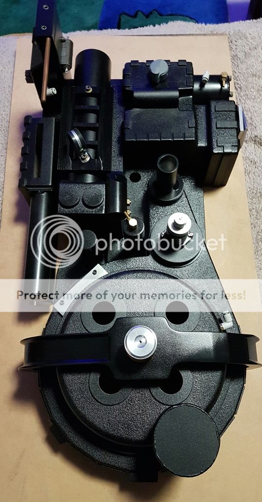
It's been a long time since my last update, and I have been busy working on my thrower whenever I can. And I have it at the point where it is worth showing. Unfortunately it wont be ready for this Halloween, but I think I am beginning to see the light at the end of the tunnel on this build
I must say that the thrower now takes the prize of most interesting & complex build for me. I've made the majority of it myself, except for the gun track, selection of knobs and acrylic barrel which are all items from the store that I purchased a fair while ago when I didn't think I would have the talent to produce.
I chased down a few of the original lamp holders from the web, and purchased the remainder from the store.
One of my larger OCD issues was the screws on the Clippard valve. I couldn't find any slotted fillister head screws locally, and the cost to import was fairly high so I decided to have a go at making them myself. So I'll start the photo updates with these.
Using a stainless steel bolt, and a set of dimensions I found on the web, I turned down the screws on the lathe. I cut the thread with a die.

After that photo I parted the screw off the bolt and turned down the head, made the slot to finish the screw.

Here is the first screw next to the same type of bolt that I used to make it.

And here is the end result.

I wouldn't want to make too many of them because it took a while, but I am happy with how they came out.
Next task was to tackle the screw in base for the hat light mounted on the gun ear. I decided to cut down the base and drill out the hole I had already drilled so that it would fit. I then epoxied the screw in base in place.


Now I didn't remember to take a heap more specific photos, so here is the end result.


The camera makes the barrel and handle look a bit out of whack, but I can assure you that they are straight.


I decided to normalise the position of the S Hook, but I'm thinking of bending it over to the right hand side.

And those little DIY screws in action.

Now for the real time consumer that made this update so late. I decided that I wanted a barrel pop mechanism, but I wanted to make one that popped based on using the green lever and twisting the front grip. I also wanted the barrel to be retracted via use of the green lever too.....
So through the use of a arduino, servo, some creative internal design I managed to achieve the following which I hope you all enjoy. (I hope the next link works for everyone as I haven't tried to post a video before, please let me know if it doesn't work and/or what i the best way to do this.)
While I know its not movie authentic I am quite pleased with the way this turned out.
I was testing the barrel extension using a spare 7.2V RC car battery I had. Later on it will be powered off the battery that powers up the rest of the pack, which will let me increase the voltage to the servo to get a faster travel action. The arduino and thrower light card will be installed in the main pack leaving me room in the thrower for a few other future extras to be installed.
I have mounted a led light board in the thrower to replace the usual led light. I found the 12LED board to too bright during tests (blindingly so), so I frosted the LEDs with a bit of steel wool and increased the resistor it comes with to reduce the current flow and brightness. I will wait to the thrower is fully painted before I fully wire it up, but when I do I will share some more photos.
I think that's about all there is to say for the time being. Thanks for reading this far. I'm looking forward to comments and constructive criticism as always.
P.

- October 27th, 2016, 10:16 am#4884417
Well that was worth waiting for! Amazing work mate. Love the pop mech
Ghostbusters is for life, not just for Halloween
GB2 Stantz/Sony Lobby Build =========> http://www.gbfans.com/community/viewtop ... =2&t=38478
GB Hero Build=========> viewtopic.php?f=2&t=40702
GB2 Stantz/Sony Lobby Build =========> http://www.gbfans.com/community/viewtop ... =2&t=38478
GB Hero Build=========> viewtopic.php?f=2&t=40702
- October 27th, 2016, 3:54 pm#4884459
Great update P, nice to see you back tinkering Wand looks great lad.
My old GB2 pack replica http://s268.photobucket.com/albums/jj16 ... ter=images
Currently building a full aluminium proton pack - w.i.p
viewtopic.php?t=38600
Now also an aluminium gb1 trap, why not!
viewtopic.php?f=3&t=42513
Currently building a full aluminium proton pack - w.i.p
viewtopic.php?t=38600
Now also an aluminium gb1 trap, why not!
viewtopic.php?f=3&t=42513
- November 1st, 2016, 5:52 am#4884917
Hi all. A small but important Halloween update on my build.
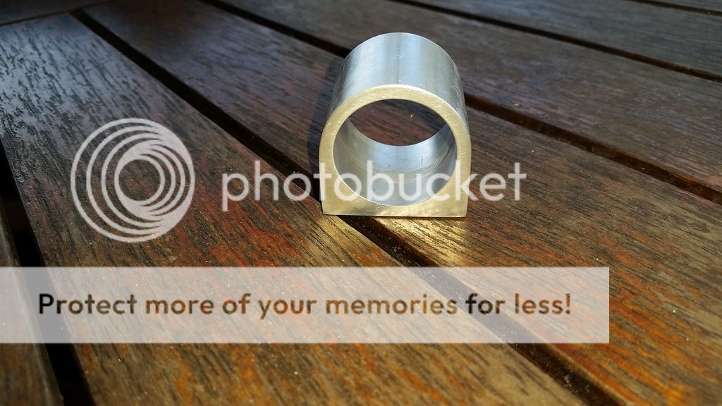
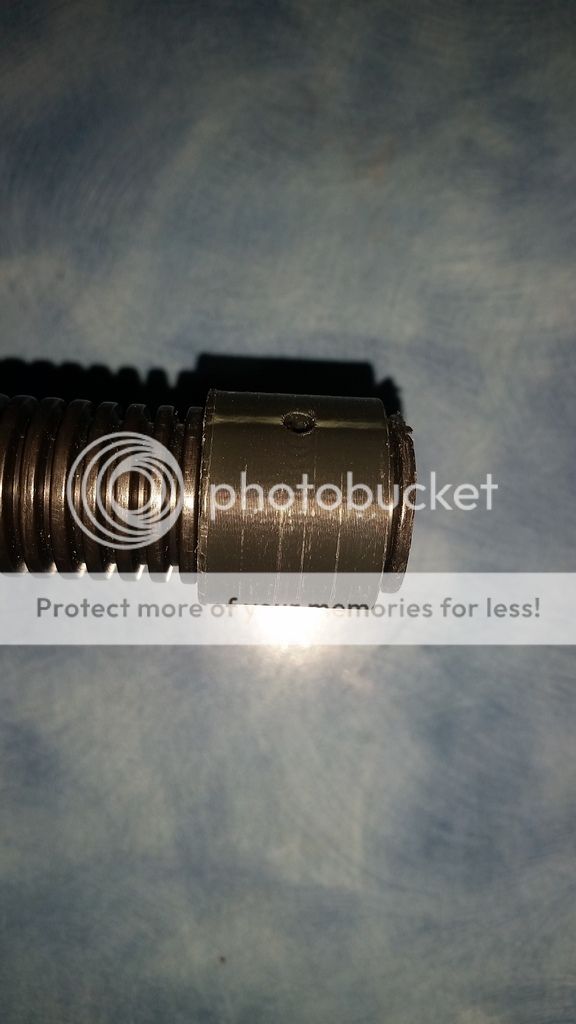
This weekend I made the hose clamp up for the pack and came up with a neat way to secure the flexible conduit a both ends. Taking inspiration from Wiz's super neat hose clamp I set about making mine from a piece of aluminum tube. The tube is the same as used on the vaccuum line. I drilled the inner bore partly out to be the same size as the inner diameter of the thrower handle so that I could develop a common way of securing the flexible conduit.
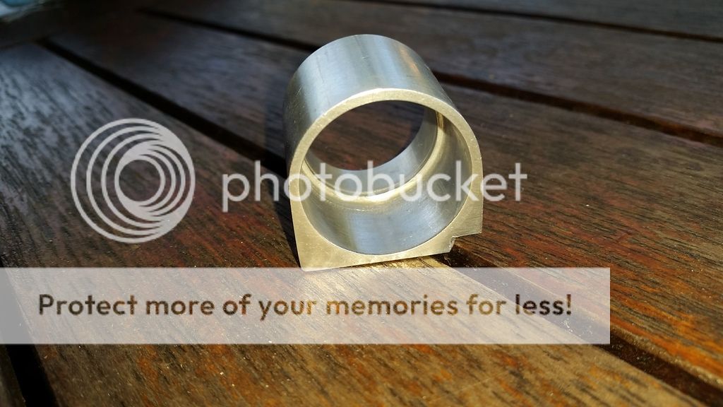
I then built up the side of the tube with welds and filled them back to square off the corners to arrive at this cool shape. Front view.
Rear view. You can see where I filled the bottom corner to sit over the pack/motherboard mounting bracket.
I then drilled and tapped holes for two small button head mounting screws.
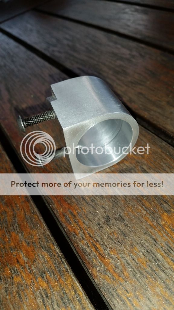
After a bit of finessing the pack cutout hole I installed the clamp.
To clamp the hose I designed this clip up using fusion360 which I have 3d printed in ABS.
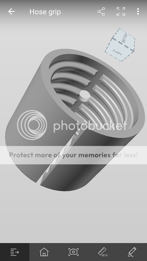
This clip goes over the flexible conduit clipping securely into the ridges.
The clip then fits with the flexible conduit neatly into both the thrower handle and pack clamp. On the thrower it is aligned so that the grip screw engages in the small hole and secures it into place. On the pack clamp side I'm going to place a similar holding screw. Once this is done I'll take a couple more photos. My 3d printed prototypes have held the conduit really securely in place. Which also let me temporarily connect my thrower and pack together for the first time... yeah!
That's all for tonight.
P.
This weekend I made the hose clamp up for the pack and came up with a neat way to secure the flexible conduit a both ends. Taking inspiration from Wiz's super neat hose clamp I set about making mine from a piece of aluminum tube. The tube is the same as used on the vaccuum line. I drilled the inner bore partly out to be the same size as the inner diameter of the thrower handle so that I could develop a common way of securing the flexible conduit.
I then built up the side of the tube with welds and filled them back to square off the corners to arrive at this cool shape. Front view.

Rear view. You can see where I filled the bottom corner to sit over the pack/motherboard mounting bracket.

I then drilled and tapped holes for two small button head mounting screws.

After a bit of finessing the pack cutout hole I installed the clamp.

To clamp the hose I designed this clip up using fusion360 which I have 3d printed in ABS.

This clip goes over the flexible conduit clipping securely into the ridges.

The clip then fits with the flexible conduit neatly into both the thrower handle and pack clamp. On the thrower it is aligned so that the grip screw engages in the small hole and secures it into place. On the pack clamp side I'm going to place a similar holding screw. Once this is done I'll take a couple more photos. My 3d printed prototypes have held the conduit really securely in place. Which also let me temporarily connect my thrower and pack together for the first time... yeah!
That's all for tonight.
P.

- November 1st, 2016, 12:31 pm#4884963
Beautiful...absolutely stunning work [emoji4][emoji106]
"...but if we're right, and we can stop this thing...then Lenny, you'll have saved the lives of MILLIONS of registered voters" - Dr. Peter Venkman

My GB1 Pack Build:http://www.gbfans.com/community/viewtop ... =2&t=40212
My GB1 Ghost Trap Build:http://www.gbfans.com/community/viewtop ... =3&t=41421
My GB1 Pack Build:http://www.gbfans.com/community/viewtop ... =2&t=40212
My GB1 Ghost Trap Build:http://www.gbfans.com/community/viewtop ... =3&t=41421
- November 1st, 2016, 2:32 pm#4884970
3d printing now eh, Heresy!!  Seriously though, thats lovely work young man
My old GB2 pack replica http://s268.photobucket.com/albums/jj16 ... ter=images
Currently building a full aluminium proton pack - w.i.p
viewtopic.php?t=38600
Now also an aluminium gb1 trap, why not!
viewtopic.php?f=3&t=42513
Currently building a full aluminium proton pack - w.i.p
viewtopic.php?t=38600
Now also an aluminium gb1 trap, why not!
viewtopic.php?f=3&t=42513
- January 6th, 2017, 6:28 am#4888281
Hi All
I know its been a long time since my last update so here is a rather large one. I have spent a fair bit of tie over the Christmas break progressing my build. In summary the main things I have done is work out the bracketing to hold all of the internals, sort out the speakers, get a battery to power the lot, do a few light and sound test runs on the pack, paint the shell and thrower.
I tried to remember to take a few more photos as I progressed, and here is a selection of what I thought are the more interesting build aspects.
Starting were I last left off....
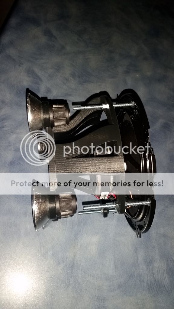
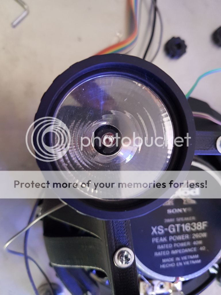
I decided to have a go at creating a mounting frame to hold the cyclotron lights using the 3D printer. The idea being that it is easier to quickly prototype designs and in the end they weigh less. He is what I eventually came up with. It is designed to mount onto larger car speaker that I will mount in the cyclotron section of the pack.
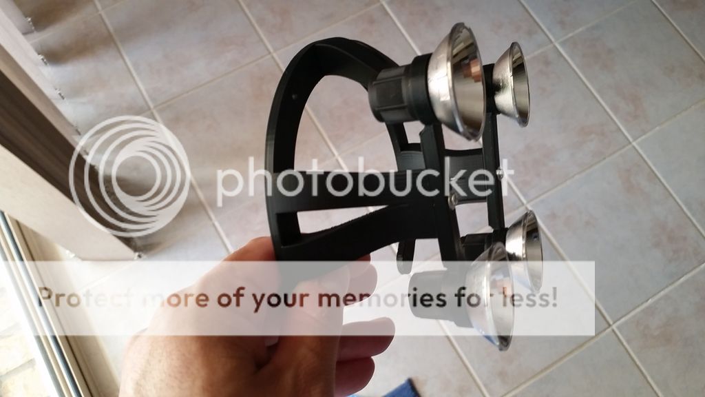
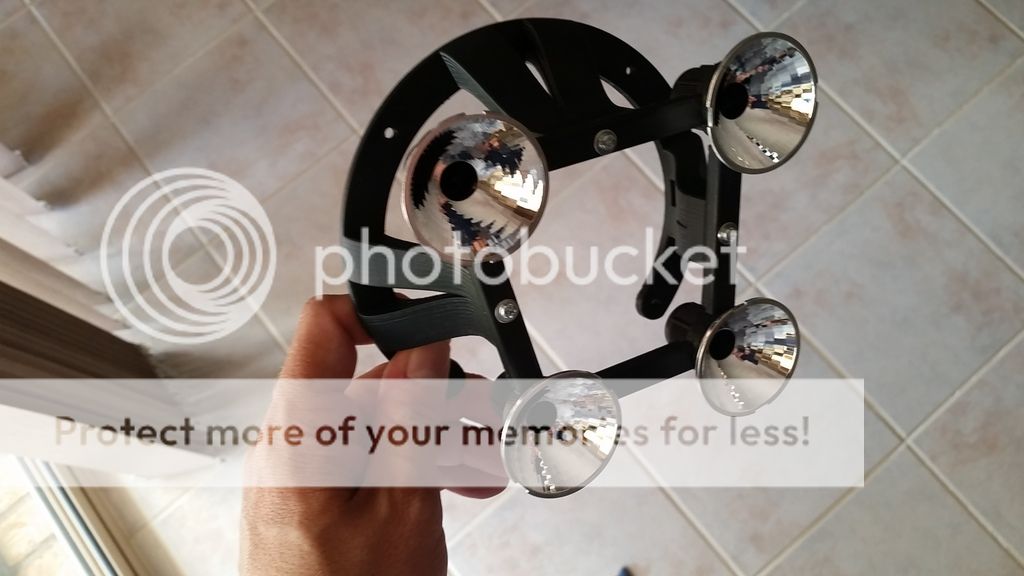
At first I was only going to use the torch light reflectors, but then I changed my mind and decided to use the reflector clear lens and ring as you will see in my later photos. Thinking being that I can frost the clear lenses up later on if I need to.
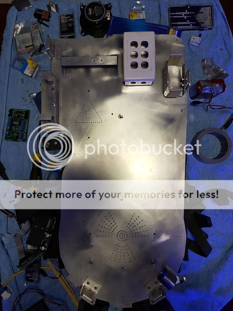
Next thing I had to do was work out where all of the internals are going to go. Because I welded up my shell in sections I have internal walls to contend with. I have removed some of these wall and made cavities to allow cables to pass through but it is still a bit of a tetris puzzle to solve.
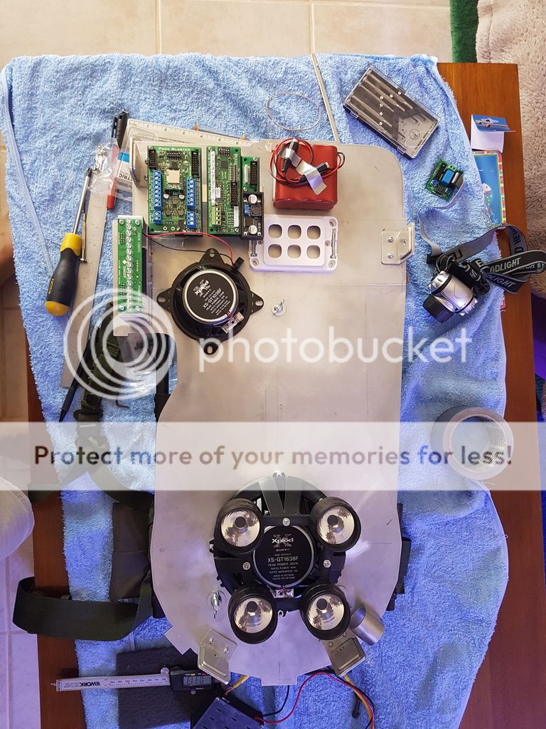
The white six port gang plate will eventually hold Ethernet jacks that I will run my wand cabling to like others have. I like how this keeps the cabling neat and easy to remove is the need arises.
I had a custom made Li-ion battery built because I was a little worried about some of the stories I had read about cheap Chinese battery exploding catching fire etc. I eventually decided to move the battery over to the gun mount cavity, and built the following bracket to hold it.
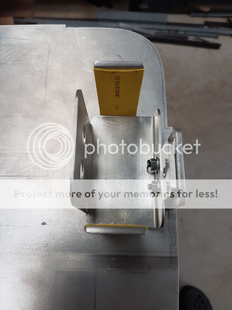
The battery bracket screws onto the L bracket that holds the shell onto the motherboard. I did it this way to save drilling additional holes in the mobo. The battery snugly fits into the bracket but later on I will place a cable-tie around the bracket and battery to hold the battery in place.
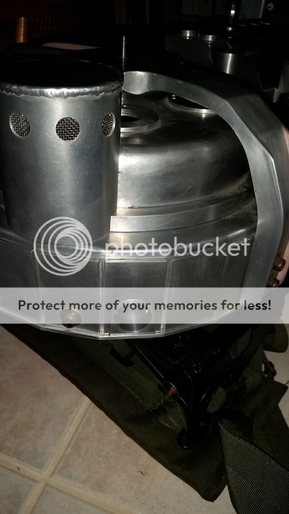
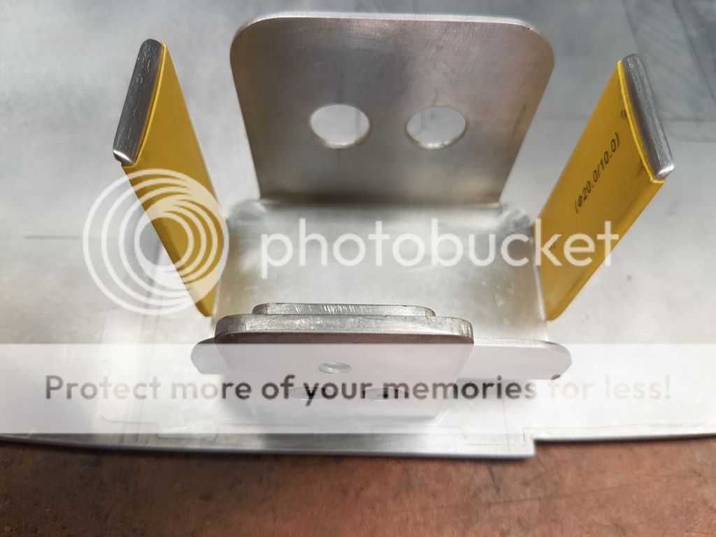
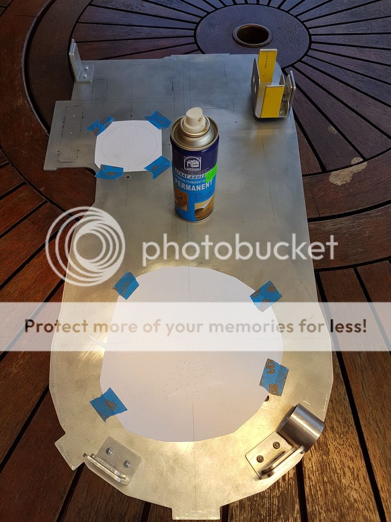
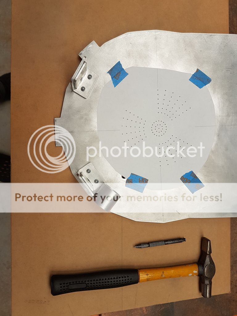
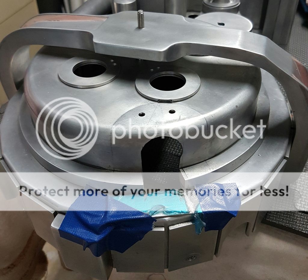
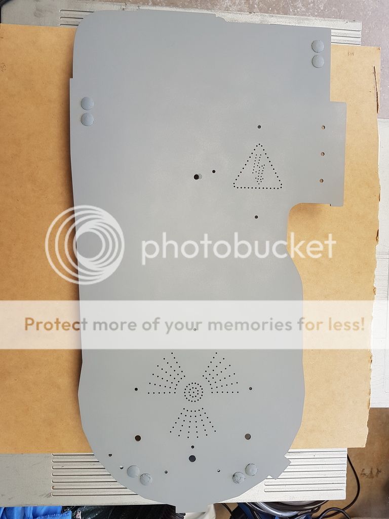
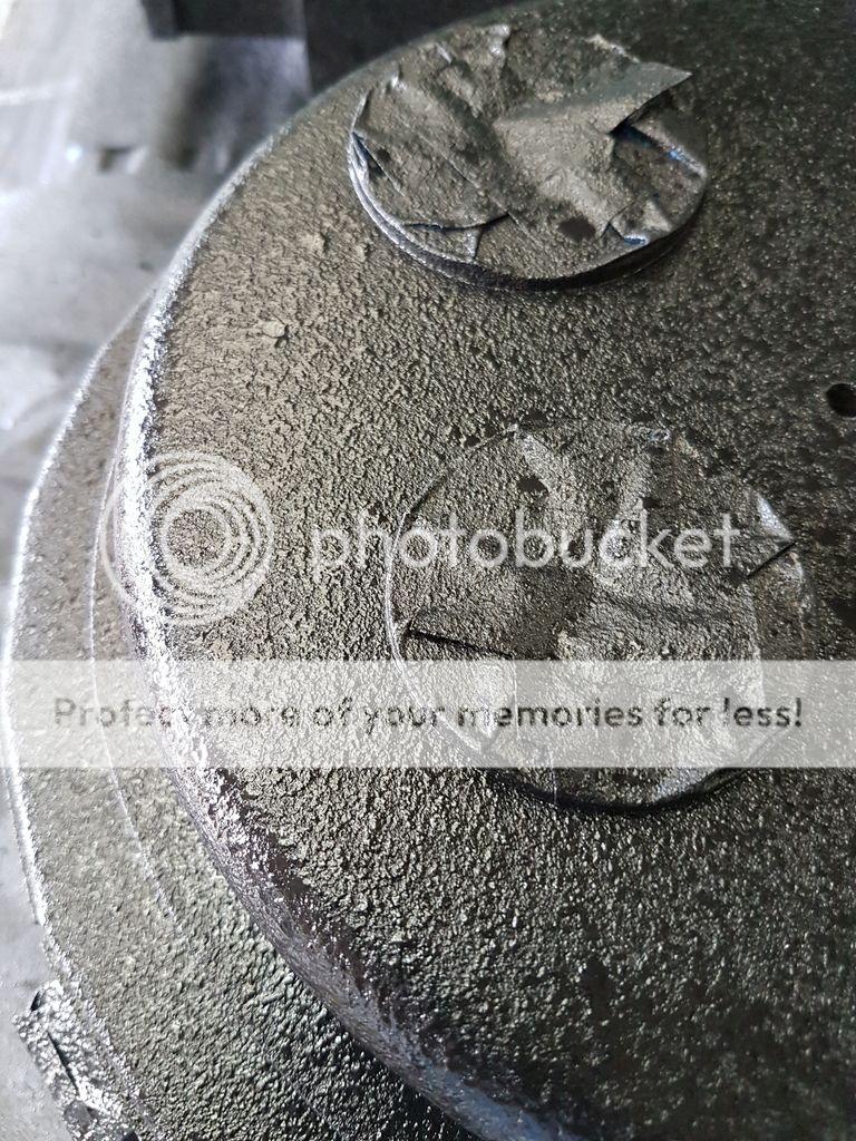
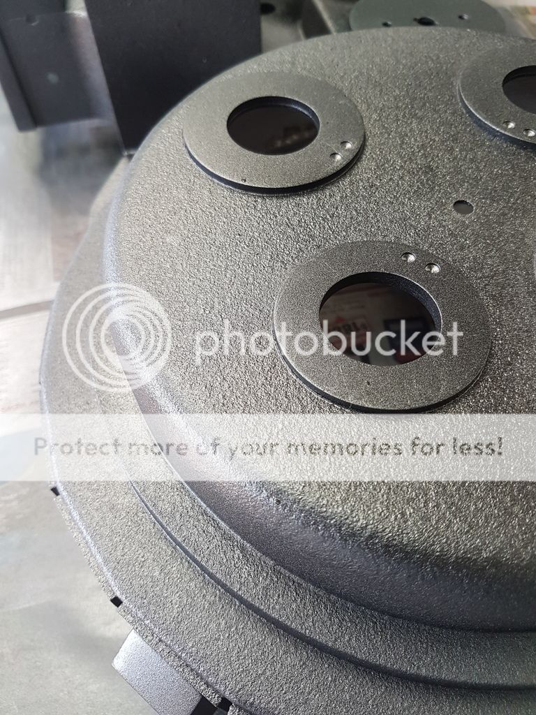
Next task was to drill out the speaker holes. Instead of going for the usual circular pattern I decided to be a little artistic here and created the nuclear symbol for the large speaker, and the danger high voltage symbol for the small speaker. I know that at the end you really cant see this detail because of the frame but I thought it would be a nice personal touch.
Hole template ready to be punched. I used a bit of spray on adhesive to hold it in place (and some blue tape for good measure) while I punched each holes position.
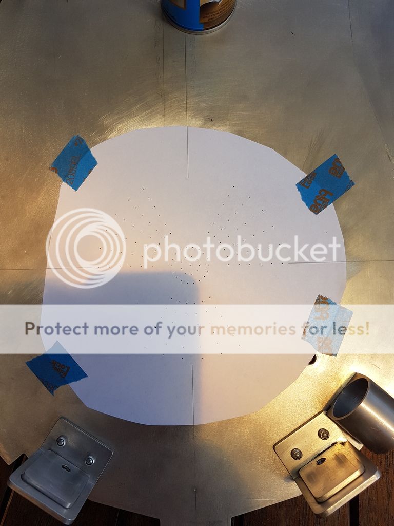
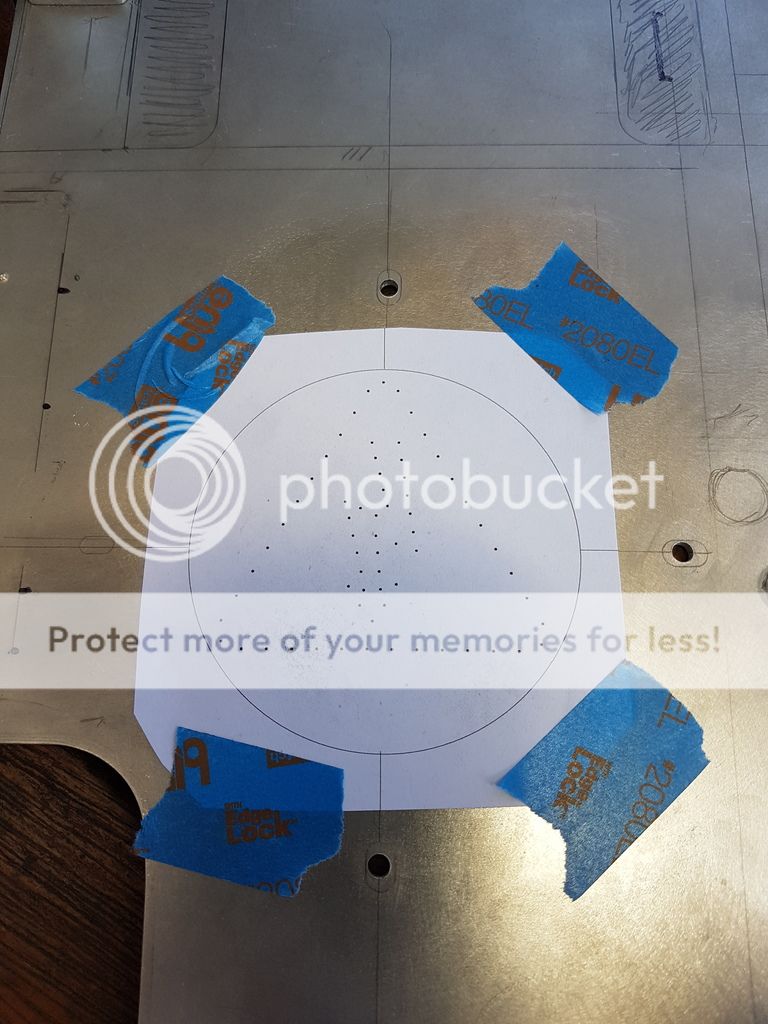
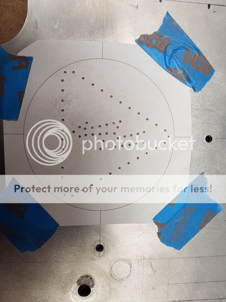
Punching done. Took a while.
A lot of drilling later.....
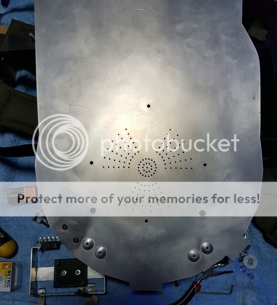

Holes drilled. You can also see the brackets to hold the power cell light circuit board and main boards in this shot.
Lights, speakers and Twinky fitted ready for bench test.
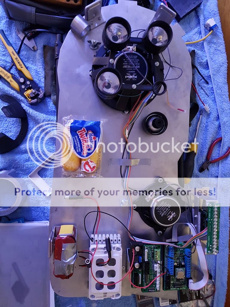
Test complete. Every thing still fits
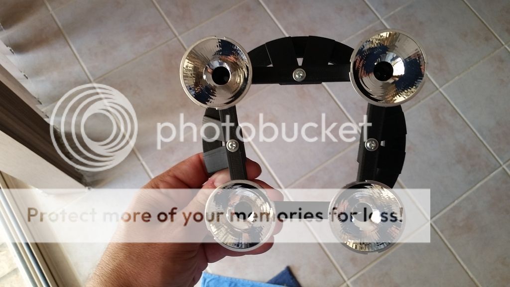
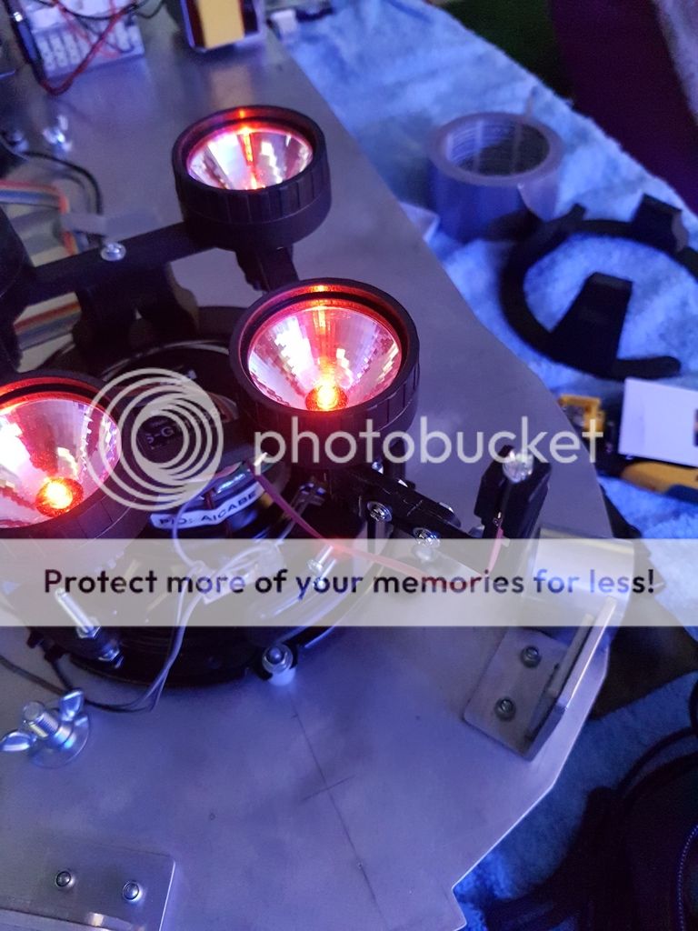
As mentioned above I decided in the end to use the torch light rims and lens. I decided to machine the rims down.
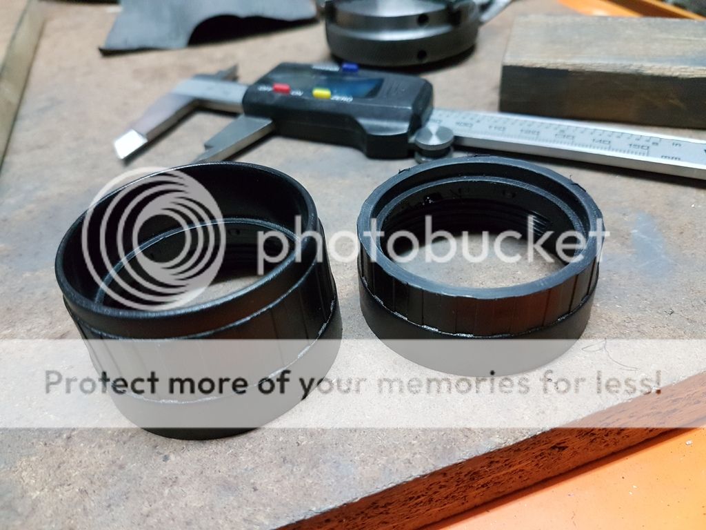
Here is how the cyclo light holder looks after cutting the rims down. Much better.
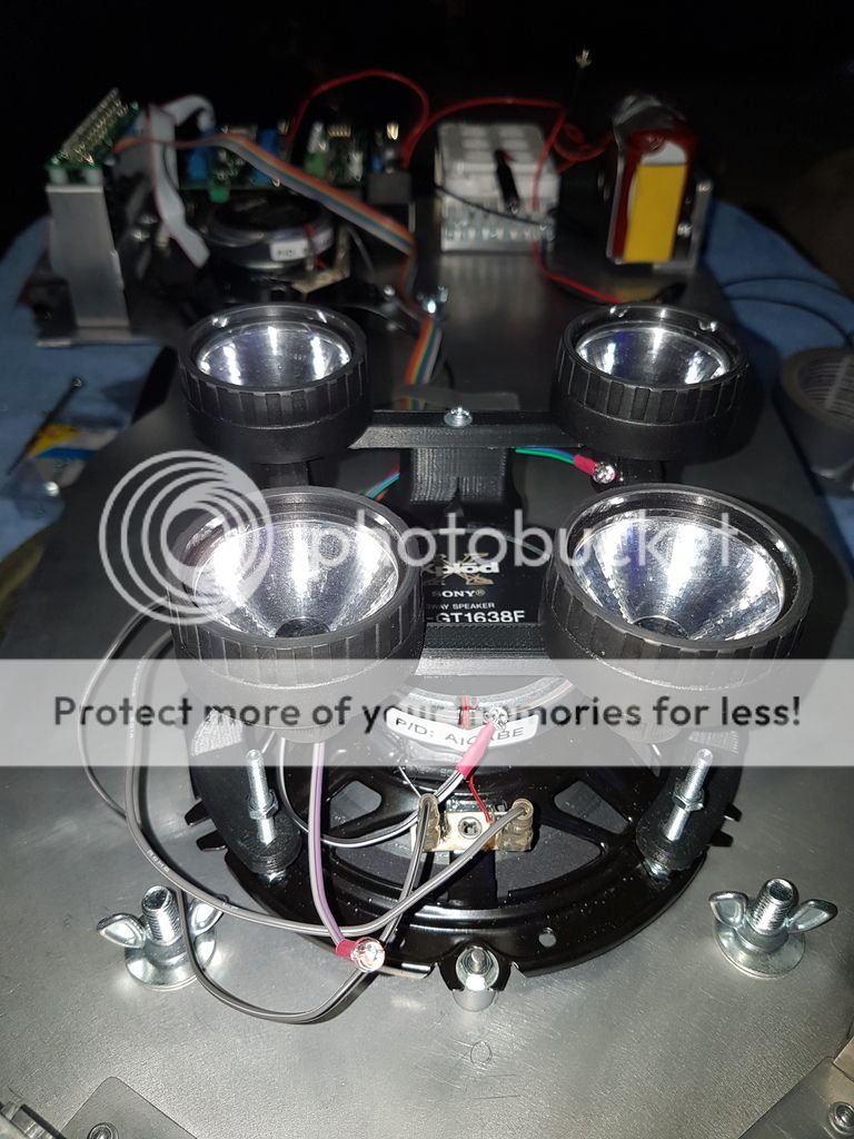
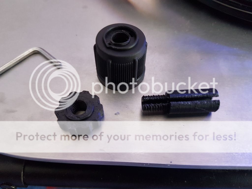
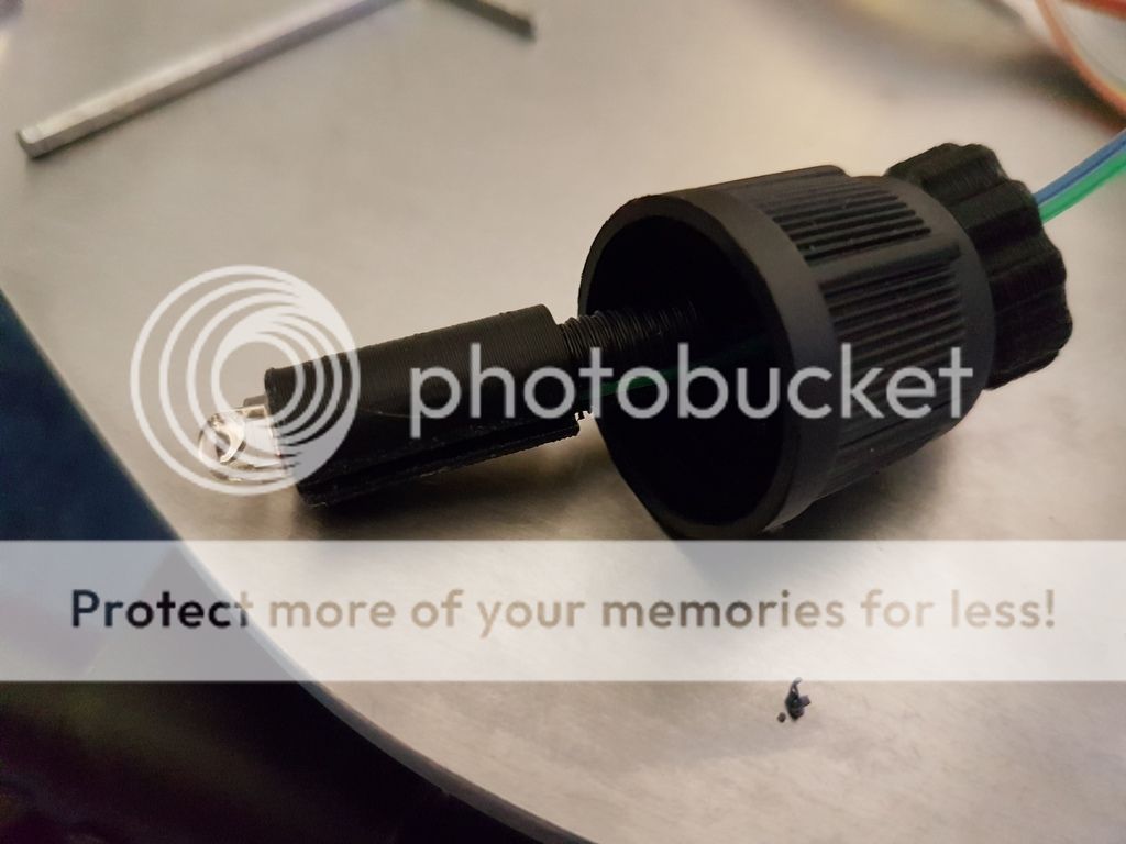
Next I 3D printed some holders to keep the cyclotron LEDs in place in each reflector. I came up with a three piece mounting arrangement.
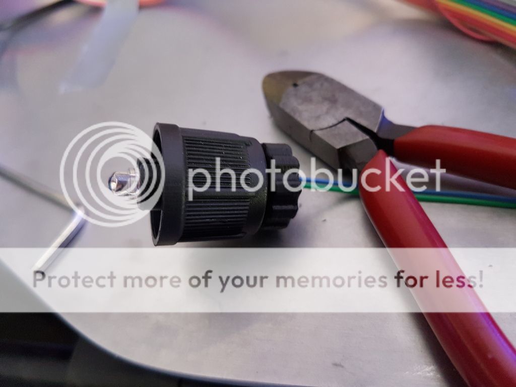
Light test with the cyclo leds centred in their reflectors.
Half way through cutting a hole between the pack internals and the N Filter.
N Filter light bracket. I'll modify this a bit later on for the ECig unit.
I mounted the V Hook and the thrower and pack became one for the first time. ALso the last shot of the pack mostly fitted and unpainted.
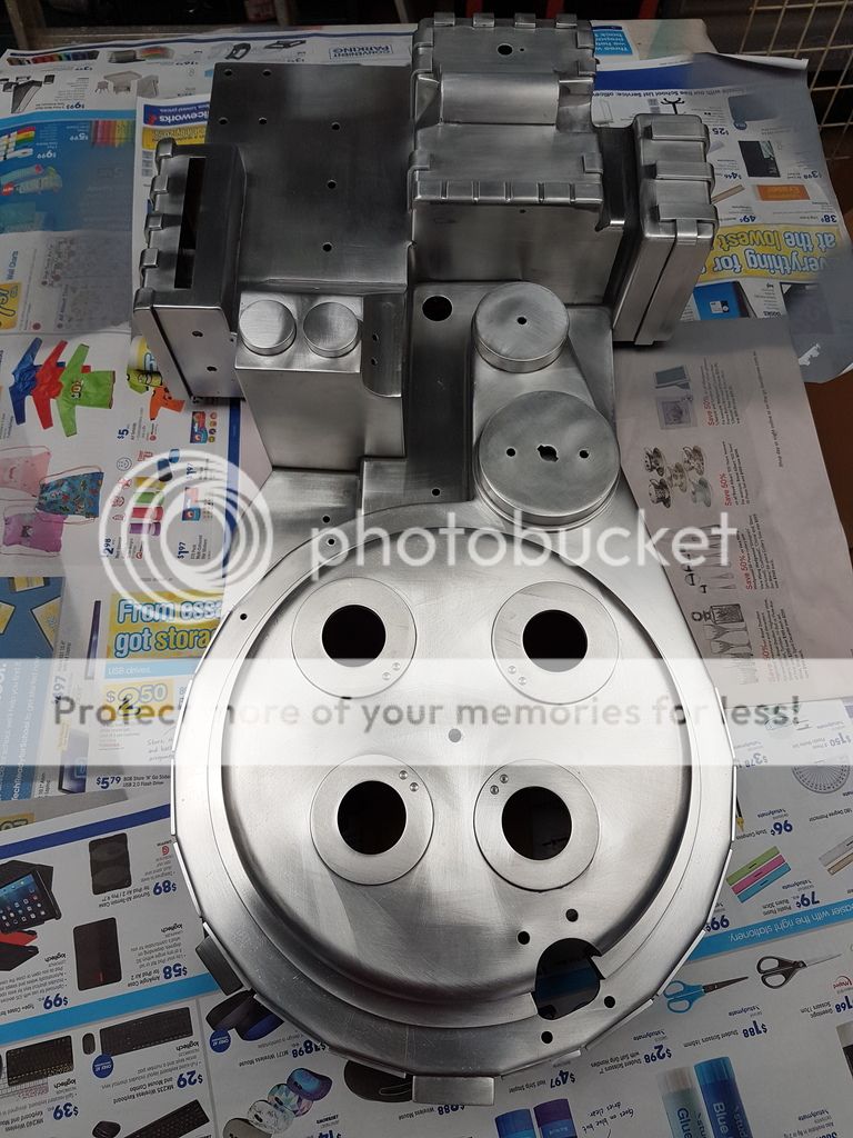
A good clean pre paint.
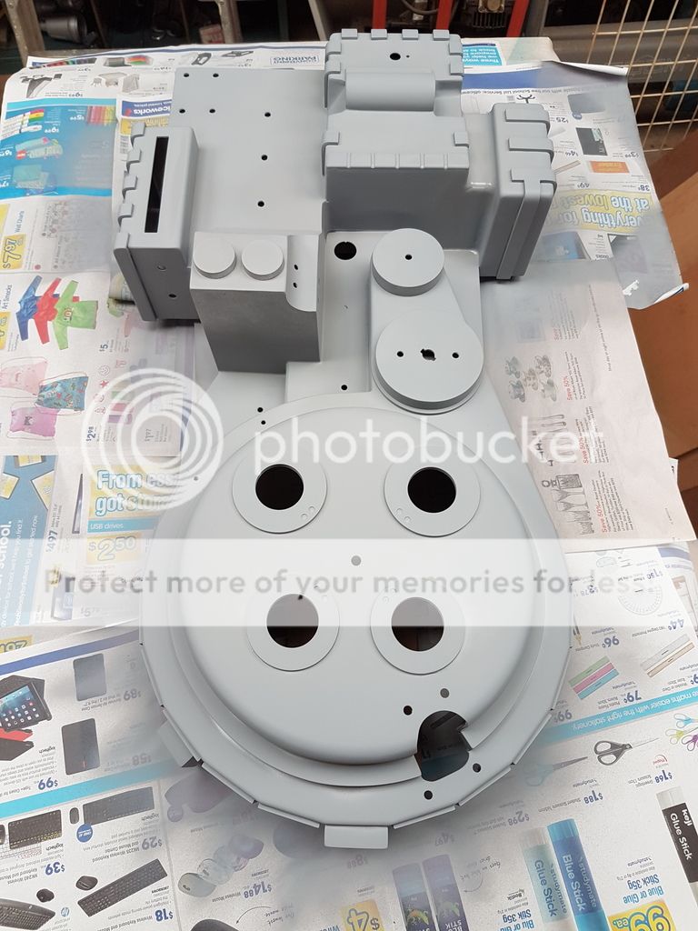
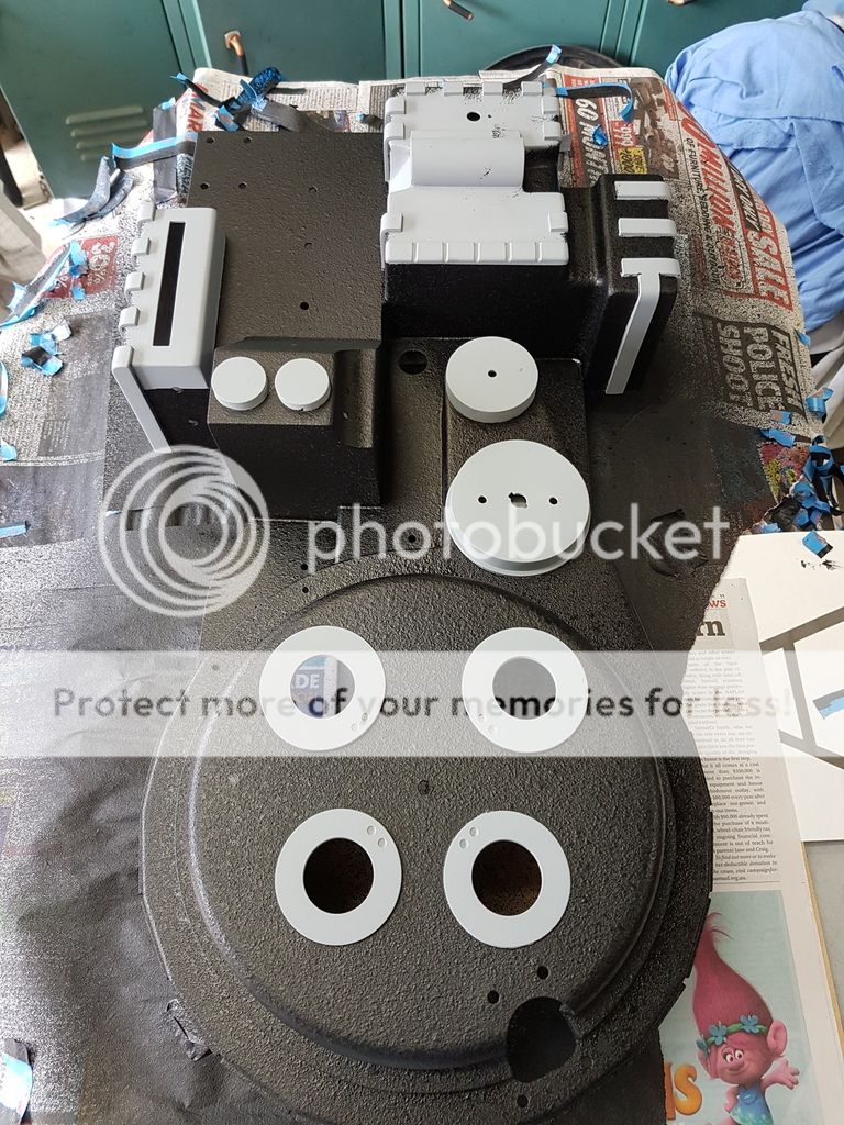
Mobo primed. I know a lot of you guys don't like priming, but I didn't want to have to do this twice as I hate painting, its generally when I stuff everything up.
Pack ready for priming.
Pack primed.
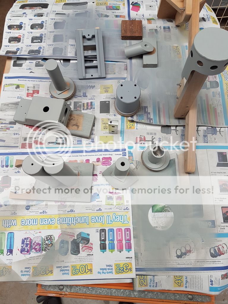
Pack parts primed. I'll be waiting a week or two after assembly before I start weathering the pack down. I should be able to cut through the primer back to the aluminium easy enough.
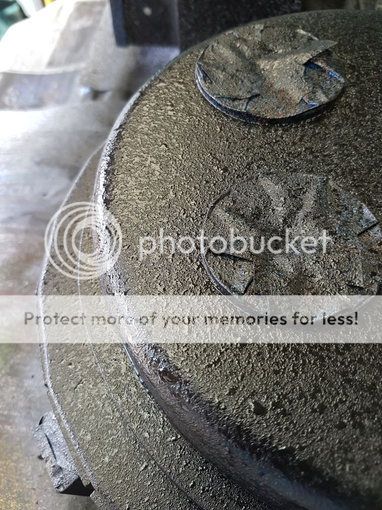
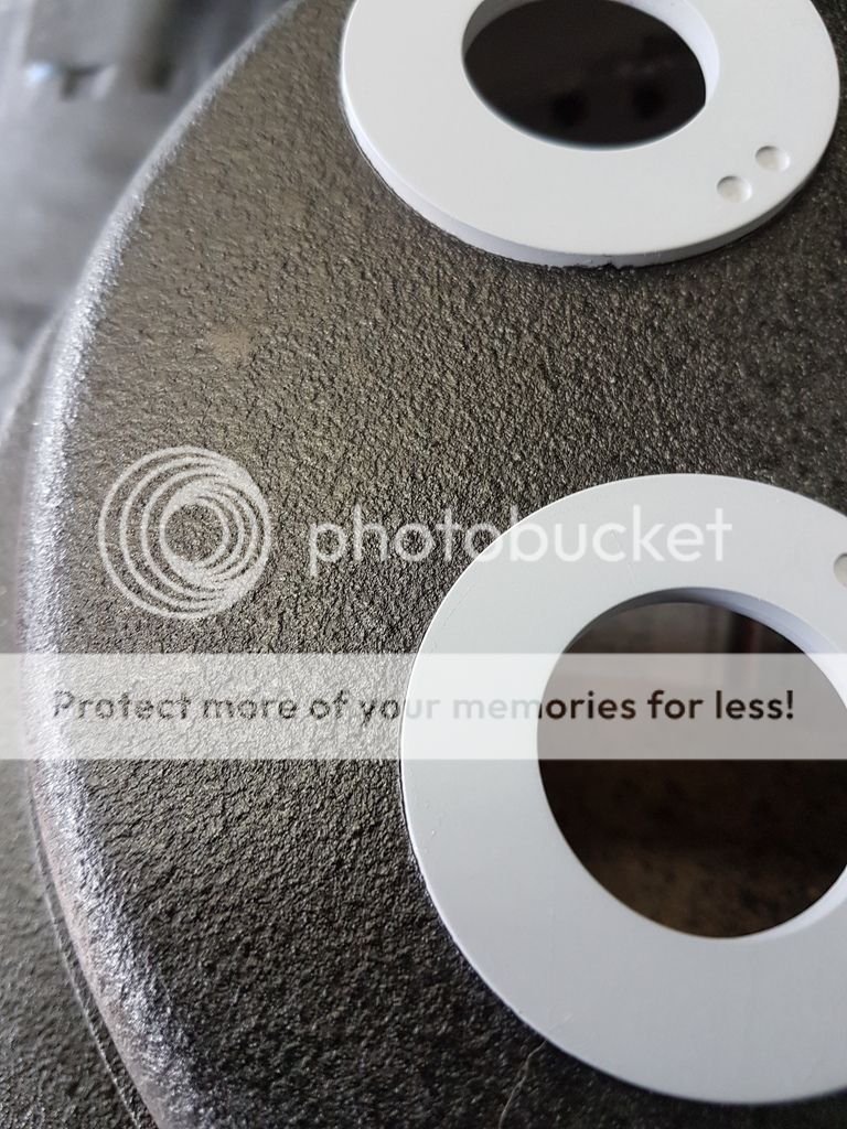
Pack ready to receive texture. For texturing I went down the truck bed liner path.
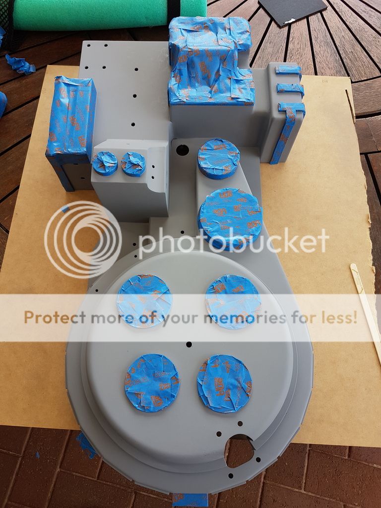
Before attempting to texture the pack, I played around with a scrap piece of metal. I found that multiple light coats, sprayed in a burst type way, i.e. spray for a second, change position, spray for a second etc to create splatter lead to an acceptable result.
Coat 1.
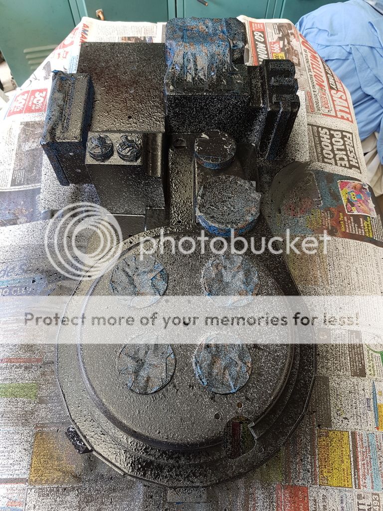
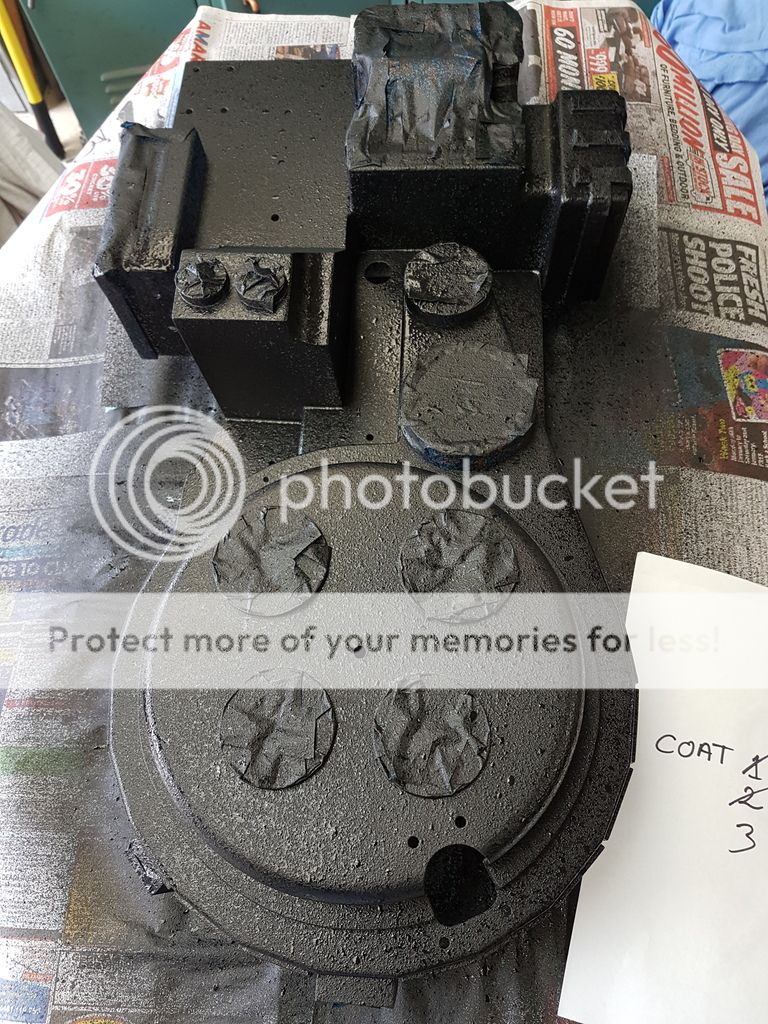
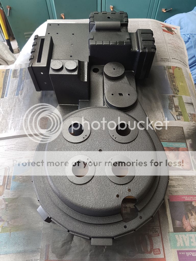
20 minutes later, coat 2.
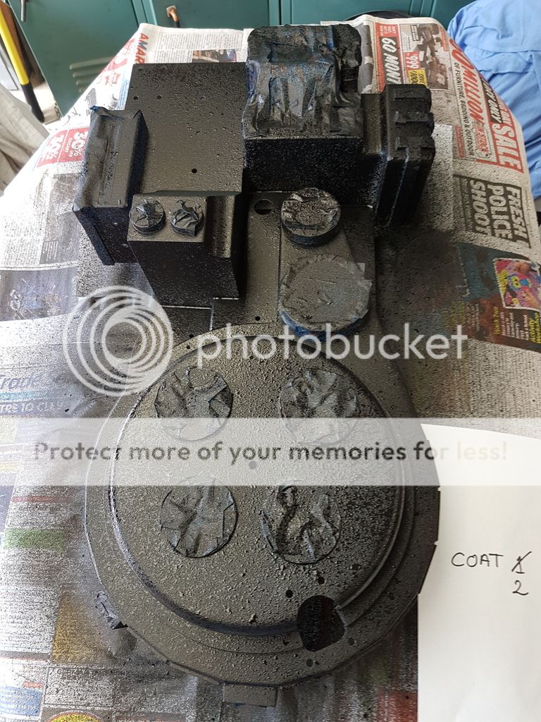
coat 3.
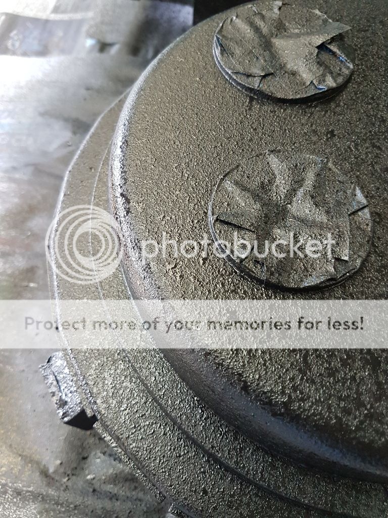
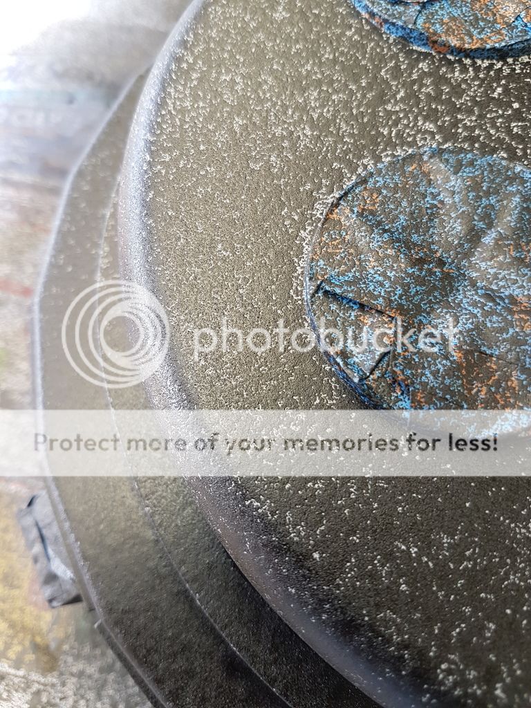
Final coat 4.
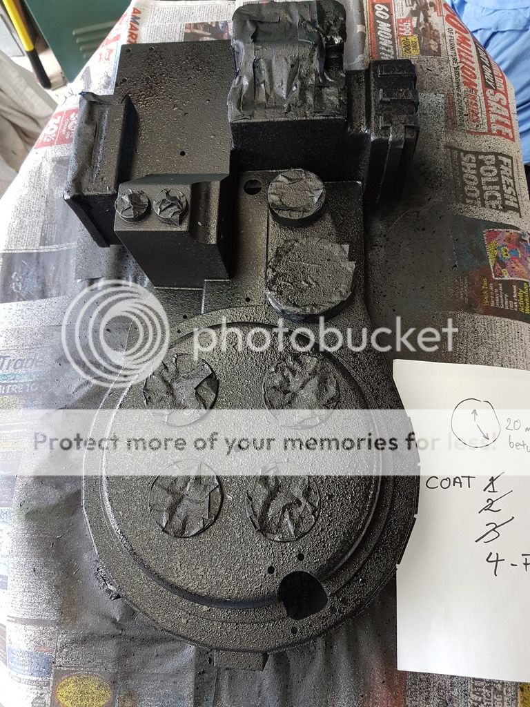
When the paint dries t dulls down.
Final satin coat applied.
Now its time to do it to the thrower, but no primer for this one. But first I have to pull the hole thing apart again. I hope I remember how it all goes back together.
At the moment the thrower paint is drying in the shed, sorry I forgot to take photos. I cant believe that I have been at this for so long, but at least now I can see the whole thing coming together with an end in sight.
That's all for now. Hopefully I will have a few more progress photos by Sunday night.
I know its been a long time since my last update so here is a rather large one. I have spent a fair bit of tie over the Christmas break progressing my build. In summary the main things I have done is work out the bracketing to hold all of the internals, sort out the speakers, get a battery to power the lot, do a few light and sound test runs on the pack, paint the shell and thrower.
I tried to remember to take a few more photos as I progressed, and here is a selection of what I thought are the more interesting build aspects.
Starting were I last left off....
I decided to have a go at creating a mounting frame to hold the cyclotron lights using the 3D printer. The idea being that it is easier to quickly prototype designs and in the end they weigh less. He is what I eventually came up with. It is designed to mount onto larger car speaker that I will mount in the cyclotron section of the pack.


At first I was only going to use the torch light reflectors, but then I changed my mind and decided to use the reflector clear lens and ring as you will see in my later photos. Thinking being that I can frost the clear lenses up later on if I need to.
Next thing I had to do was work out where all of the internals are going to go. Because I welded up my shell in sections I have internal walls to contend with. I have removed some of these wall and made cavities to allow cables to pass through but it is still a bit of a tetris puzzle to solve.

The white six port gang plate will eventually hold Ethernet jacks that I will run my wand cabling to like others have. I like how this keeps the cabling neat and easy to remove is the need arises.
I had a custom made Li-ion battery built because I was a little worried about some of the stories I had read about cheap Chinese battery exploding catching fire etc. I eventually decided to move the battery over to the gun mount cavity, and built the following bracket to hold it.


The battery bracket screws onto the L bracket that holds the shell onto the motherboard. I did it this way to save drilling additional holes in the mobo. The battery snugly fits into the bracket but later on I will place a cable-tie around the bracket and battery to hold the battery in place.
Next task was to drill out the speaker holes. Instead of going for the usual circular pattern I decided to be a little artistic here and created the nuclear symbol for the large speaker, and the danger high voltage symbol for the small speaker. I know that at the end you really cant see this detail because of the frame but I thought it would be a nice personal touch.
Hole template ready to be punched. I used a bit of spray on adhesive to hold it in place (and some blue tape for good measure) while I punched each holes position.


Punching done. Took a while.


A lot of drilling later.....


Holes drilled. You can also see the brackets to hold the power cell light circuit board and main boards in this shot.

Lights, speakers and Twinky fitted ready for bench test.

Test complete. Every thing still fits

As mentioned above I decided in the end to use the torch light rims and lens. I decided to machine the rims down.

Here is how the cyclo light holder looks after cutting the rims down. Much better.

Next I 3D printed some holders to keep the cyclotron LEDs in place in each reflector. I came up with a three piece mounting arrangement.


Light test with the cyclo leds centred in their reflectors.
Half way through cutting a hole between the pack internals and the N Filter.

N Filter light bracket. I'll modify this a bit later on for the ECig unit.

I mounted the V Hook and the thrower and pack became one for the first time. ALso the last shot of the pack mostly fitted and unpainted.

A good clean pre paint.

Mobo primed. I know a lot of you guys don't like priming, but I didn't want to have to do this twice as I hate painting, its generally when I stuff everything up.

Pack ready for priming.

Pack primed.

Pack parts primed. I'll be waiting a week or two after assembly before I start weathering the pack down. I should be able to cut through the primer back to the aluminium easy enough.

Pack ready to receive texture. For texturing I went down the truck bed liner path.

Before attempting to texture the pack, I played around with a scrap piece of metal. I found that multiple light coats, sprayed in a burst type way, i.e. spray for a second, change position, spray for a second etc to create splatter lead to an acceptable result.
Coat 1.


20 minutes later, coat 2.


coat 3.


Final coat 4.


When the paint dries t dulls down.


Final satin coat applied.


Now its time to do it to the thrower, but no primer for this one. But first I have to pull the hole thing apart again. I hope I remember how it all goes back together.

At the moment the thrower paint is drying in the shed, sorry I forgot to take photos. I cant believe that I have been at this for so long, but at least now I can see the whole thing coming together with an end in sight.
That's all for now. Hopefully I will have a few more progress photos by Sunday night.
twmedford23, barison82 liked this
- January 7th, 2017, 3:00 am#4888306
Well that was worth waiting for. Incredible work dude. The texture came out amazing!!
Ghostbusters is for life, not just for Halloween
GB2 Stantz/Sony Lobby Build =========> http://www.gbfans.com/community/viewtop ... =2&t=38478
GB Hero Build=========> viewtopic.php?f=2&t=40702
GB2 Stantz/Sony Lobby Build =========> http://www.gbfans.com/community/viewtop ... =2&t=38478
GB Hero Build=========> viewtopic.php?f=2&t=40702
- January 7th, 2017, 4:42 am#4888307
Thanks Venkman's Swagger.
I was a bit worried that there may have been a bit too much texture but I think it came out ok in the end. I keep finding myself looking at the pack thinking wow I made that.
Unfortunately no further progress today as other things took priority. I guess that the upside is the paint had more time to cure.
Pete
twmedford23 liked this
- January 7th, 2017, 10:37 pm#4888332
The spray texture does flatten out as it dries so it's understandable feeling like you might have sprayed too much or not enough
- January 8th, 2017, 5:25 am#4888336
You're welcome Pete. I must say that I love the custom speaker grilles
Ghostbusters is for life, not just for Halloween
GB2 Stantz/Sony Lobby Build =========> http://www.gbfans.com/community/viewtop ... =2&t=38478
GB Hero Build=========> viewtopic.php?f=2&t=40702
GB2 Stantz/Sony Lobby Build =========> http://www.gbfans.com/community/viewtop ... =2&t=38478
GB Hero Build=========> viewtopic.php?f=2&t=40702
- January 11th, 2017, 7:12 am#4888514
STUNNING work - speechless. Internals are so well done, such tidy, professional work! I love those custom speaker grilles too. And the texture came out beautifully. Awesome update
"...but if we're right, and we can stop this thing...then Lenny, you'll have saved the lives of MILLIONS of registered voters" - Dr. Peter Venkman
My GB1 Pack Build:http://www.gbfans.com/community/viewtop ... =2&t=40212
My GB1 Ghost Trap Build:http://www.gbfans.com/community/viewtop ... =3&t=41421
My GB1 Pack Build:http://www.gbfans.com/community/viewtop ... =2&t=40212
My GB1 Ghost Trap Build:http://www.gbfans.com/community/viewtop ... =3&t=41421
- January 11th, 2017, 3:47 pm#4888534
Thanks for the kind comments VS and Barison it's nice to hear that others think I have done an ok job on this build.
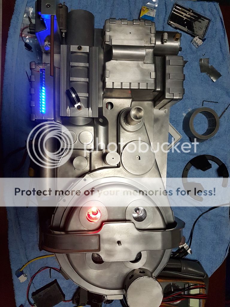
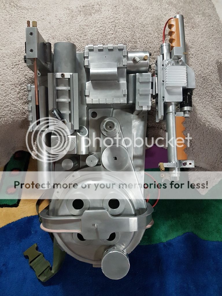
Just one quick pic update from last weekends efforts. Basically I put all of the painted parts back on the shell. I made a small tapered rubber gasket to square out the injector tubes to the power cell which came out ok.
One other minor thing is that the textured bed liner paint still has a slight tack to it. It seems to need a lot of time to fully dry/cure, which might be due to the temperature and humidity in Brisbane at the moment. The temperature has been mid 30C for weeks with a humidity around 70 - 80+ %. Ì would have to wait until June to paint for humidity around 50%. I just hope it fully cures because I would hate to have to do it all again.
That's all for now.
Just one quick pic update from last weekends efforts. Basically I put all of the painted parts back on the shell. I made a small tapered rubber gasket to square out the injector tubes to the power cell which came out ok.

One other minor thing is that the textured bed liner paint still has a slight tack to it. It seems to need a lot of time to fully dry/cure, which might be due to the temperature and humidity in Brisbane at the moment. The temperature has been mid 30C for weeks with a humidity around 70 - 80+ %. Ì would have to wait until June to paint for humidity around 50%. I just hope it fully cures because I would hate to have to do it all again.
That's all for now.
barison82 liked this
- January 12th, 2017, 2:49 am#4888550
Here's hoping the humid stays higher and you need to soda blast all that black crap off to reveal all the beautify aluminium that makes this pack special.

- January 12th, 2017, 4:48 am#4888554
Meaty wrote:Here's hoping the humid stays higher and you need to soda blast all that black crap off to reveal all the beautify aluminium that makes this pack special.A charming first impression, Meaty.

- January 12th, 2017, 4:52 am#4888555
Meaty wrote:Here's hoping the humid stays higher and you need to soda blast all that black crap off to reveal all the beautify aluminium that makes this pack special.What makes this pack special is that it is his! Can't get much more special than that. Comments like this really aren't needed or called for within the community man. Not cool
Ghostbusters is for life, not just for Halloween
GB2 Stantz/Sony Lobby Build =========> http://www.gbfans.com/community/viewtop ... =2&t=38478
GB Hero Build=========> viewtopic.php?f=2&t=40702
GB2 Stantz/Sony Lobby Build =========> http://www.gbfans.com/community/viewtop ... =2&t=38478
GB Hero Build=========> viewtopic.php?f=2&t=40702
Pchrisbosh1 GB1 Hero Shell 3D Model for 3D Printing! Updated 4/23/04
 - By pchrisbosh1
Hey guys I've been doing some updating and adding […]
Ghostbusters Day 2024
 - By tylergfoster
Even if Frozen Empire somehow made a billion dol[…]
Some films doing better outside of the U.S. than others?
- By tylergfosterTo repost what I said in the other thread: I don'[…]
GBFANS Ghostlabs light kit
Hey everybody, this is my first post so let me kno[…]